
Flix (flight + X) — open source ESP32-based quadcopter made from scratch.
| Version 1.1 (3D-printed frame) | Version 0 |
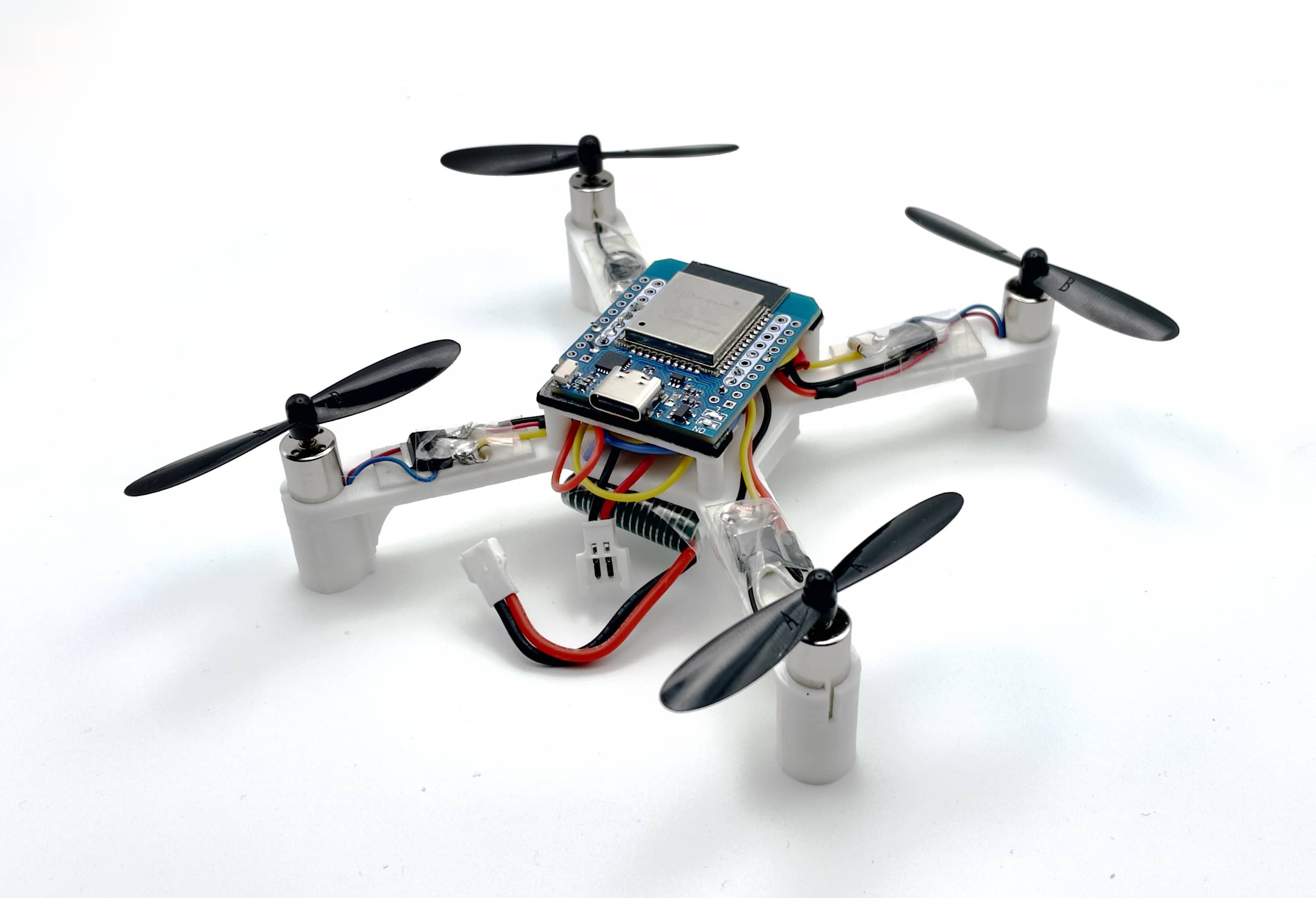 | 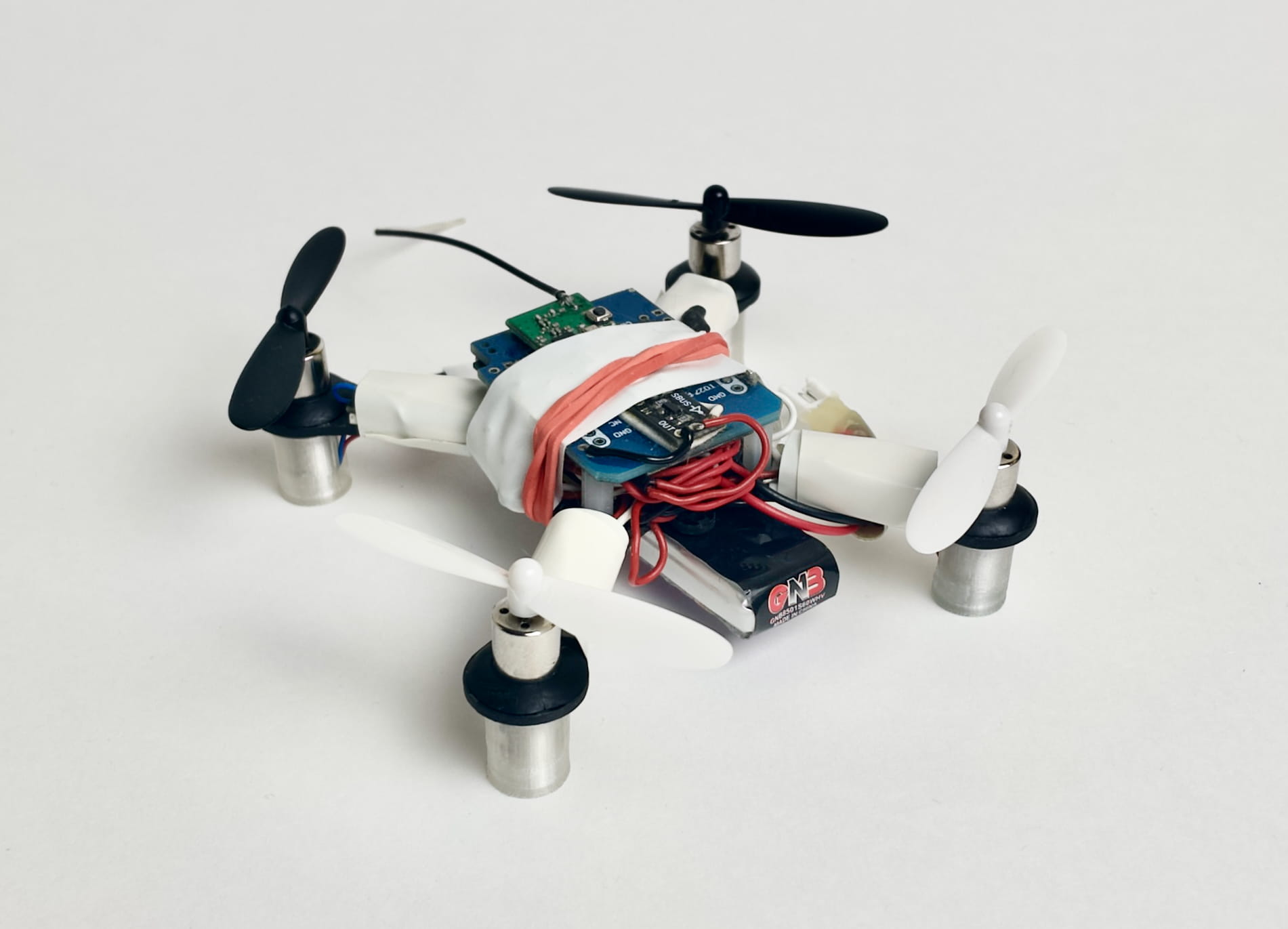 |
Features
- Dedicated for education and research.
- Made from general-purpose components.
- Simple and clean source code in Arduino (<2k lines firmware).
- Communication using MAVLink protocol over Wi-Fi or ESP-NOW.
- Control with USB gamepad, remote control or smartphone.
- Wireless command line interface and analyzing.
- Precise simulation with Gazebo.
- Python library for scripting and automatic flights.
- Textbook on flight control theory and practice (in development).
- Position control (planned).
It actually flies
See detailed demo video: https://youtu.be/hT46CZ1CgC4.
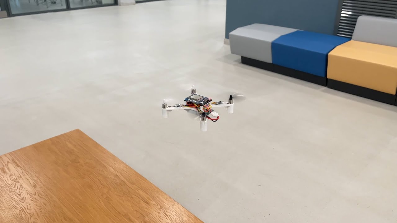
Version 0 demo video: https://youtu.be/8GzzIQ3C6DQ.

Usage in education (RoboCamp 2025): https://youtu.be/Wd3yaorjTx0.
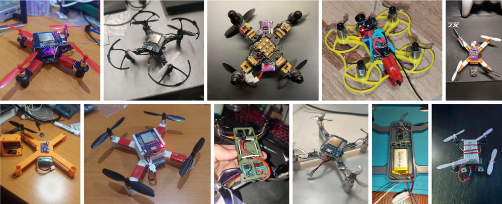
See the user builds gallery:
PCB
The official PCB (Flix2) is in development now. Follow the project's channel to track the progress.
Outdoor flights demo video of the current prototype:
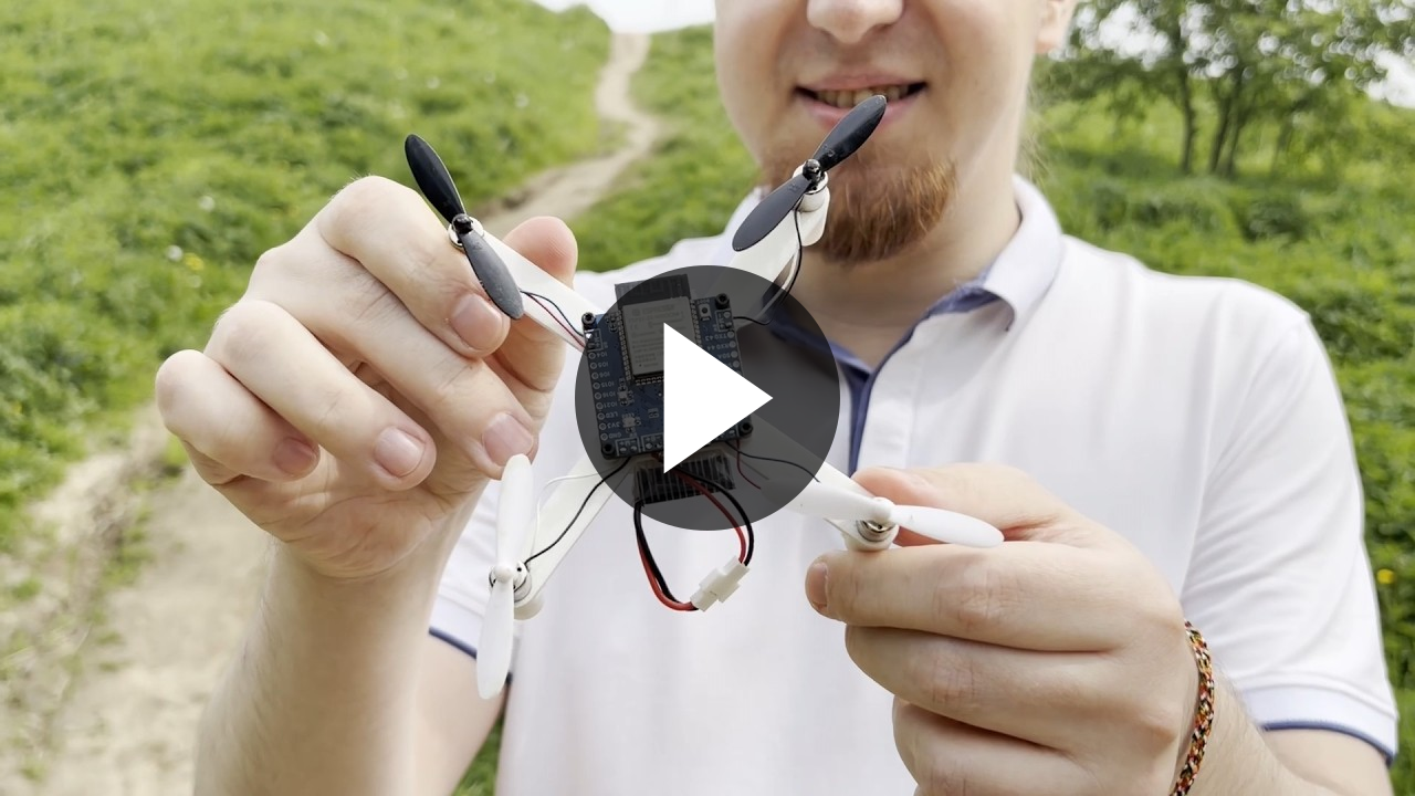
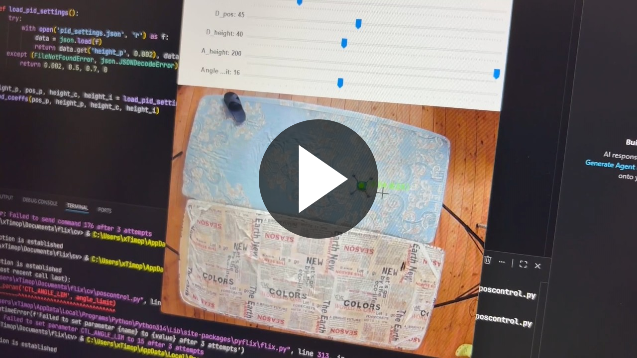
Position control
The position control feature is in development. RoboCamp 2026 demo (using an overhead camera, sources):
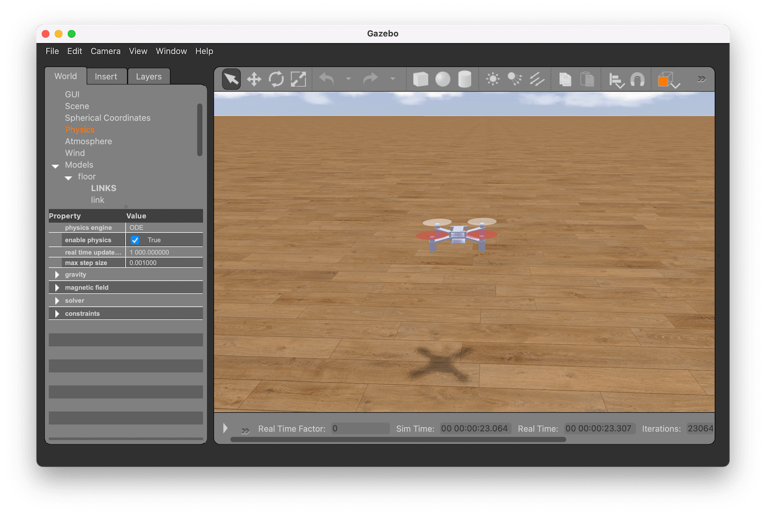
Simulation
The simulator is implemented using Gazebo and runs the original Arduino code:
Documentation articles
Additional articles:
Components
| Type | Part | Image | Quantity |
|---|---|---|---|
| Microcontroller board | ESP32 Mini. ESP32-S3/ESP32-C3 boards are also supported. | 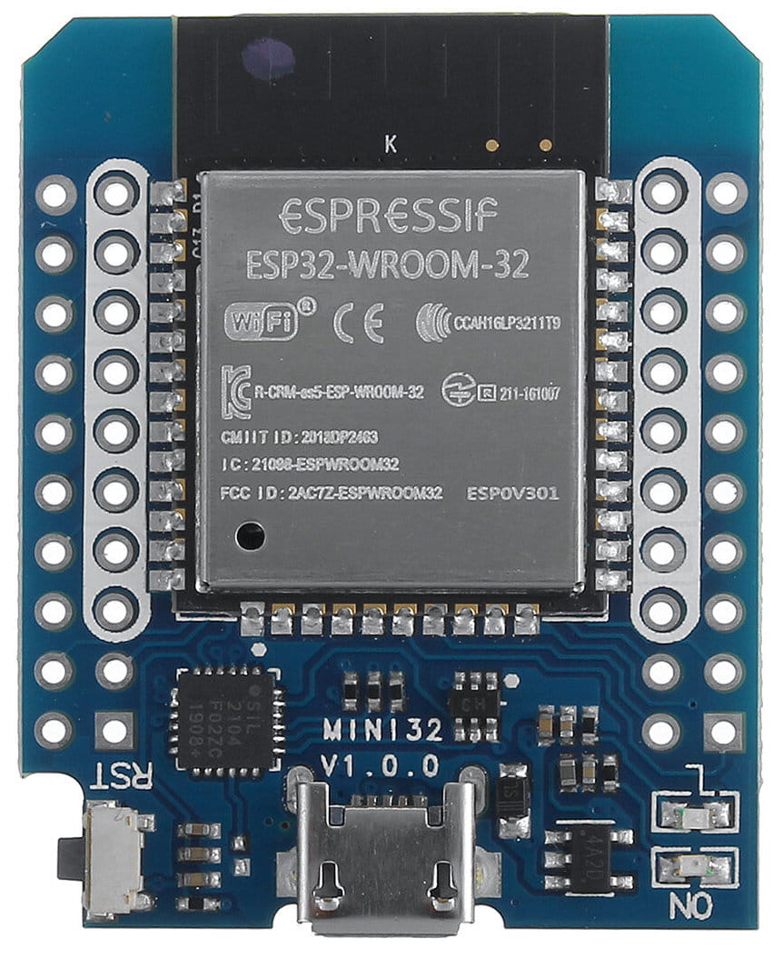 | 1 |
| IMU (and barometer¹) board | GY‑91, MPU-9265 (or other MPU‑9250/MPU‑6500 board) ICM20948V2 (ICM‑20948) GY-521 (MPU-6050) | 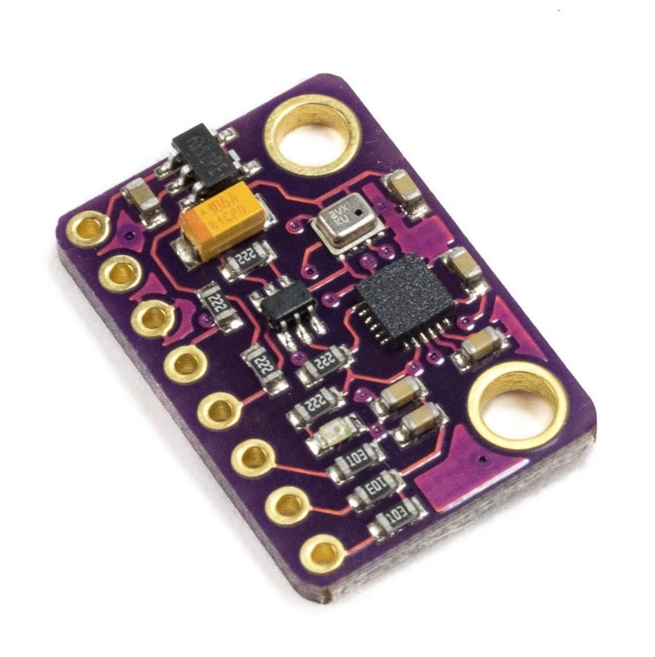 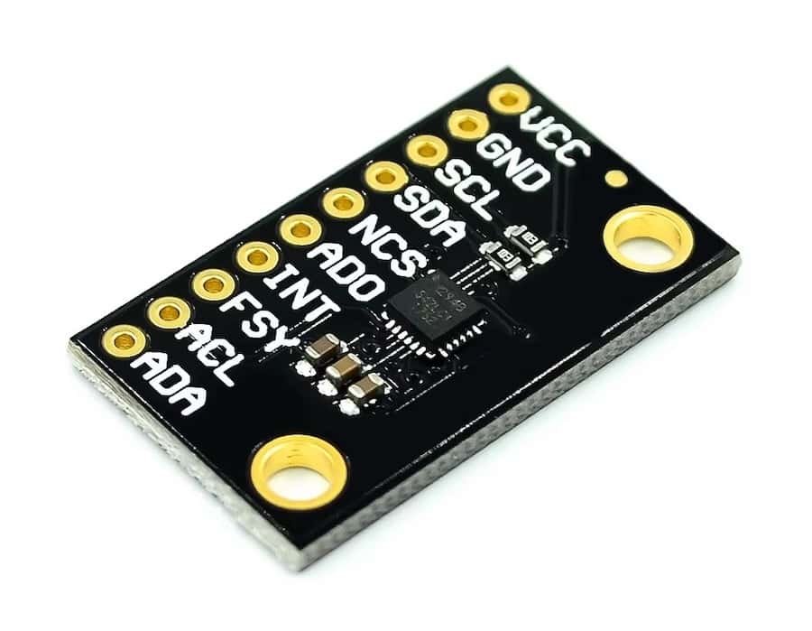 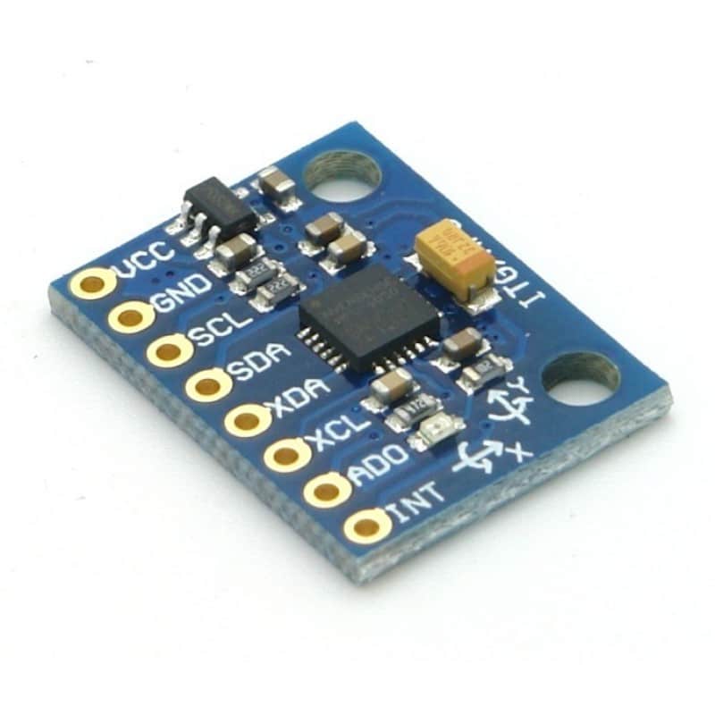 | 1 |
| Boost converter (optional, for more stable power supply) | 5V output | 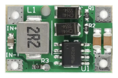 | 1 |
| Motor | 8520 3.7V brushed motor. Motor with exact 3.7V voltage is needed, not ranged working voltage (3.7V — 6V). Make sure the motor shaft diameter and propeller hole diameter match! | 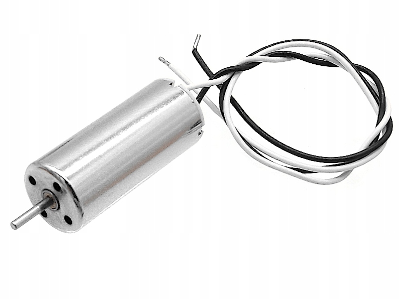 | 4 |
| Propeller | 55 mm or 65 mm | 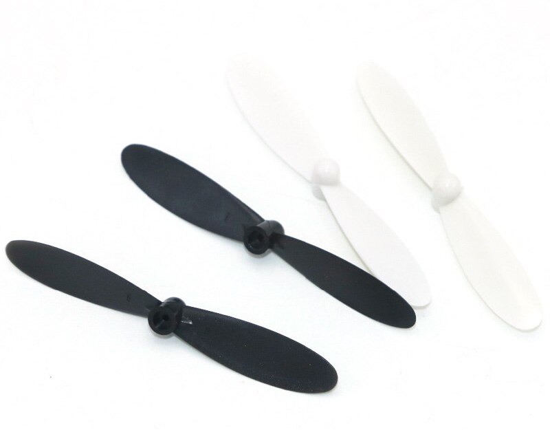 | 4 |
| MOSFET (transistor) | UMW 100N03A or analog. Warning: don't use KIA 100N03A or other manufacturers, they might not work! | 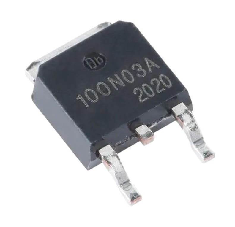 | 4 |
| Pull-down resistor Voltage measurement resistor | 10 kΩ | 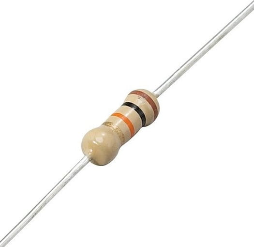 | 6 |
| 3.7V Li-Po battery | LW 952540 (or any compatible by the size). Make sure the battery has enough discharge rate and capacity — 25C with 1000 mAh or more is recommended! | 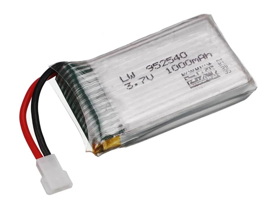 | 1 |
| Battery connector cable | MX2.0 2P female | 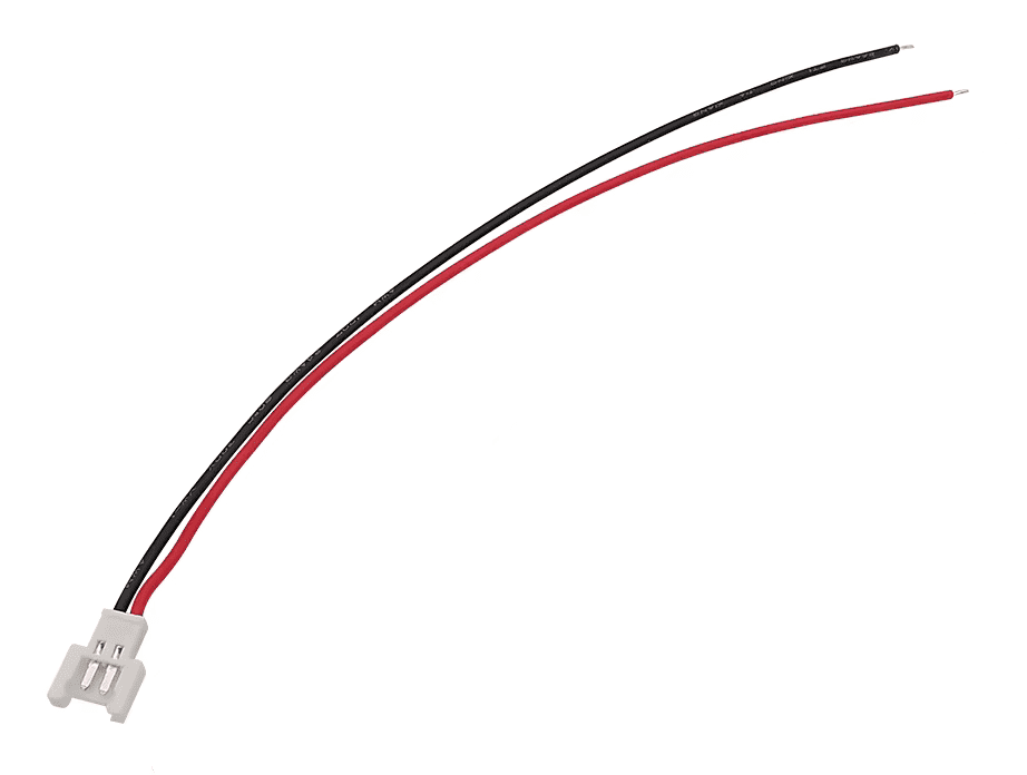 | 1 |
| Li-Po Battery charger | Any | 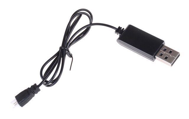 | 1 |
| Screws for IMU board mounting | M3x5 | 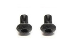 | 2 |
| Screws for frame assembly | M1.4x5 | 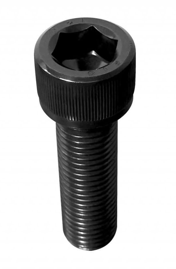 | 4 |
| Frame main part | 3D printed²: stl stepRecommended settings: layer 0.2 mm, line 0.4 mm, infill 100%. | 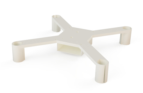 | 1 |
| Frame top part | 3D printed: stl step | 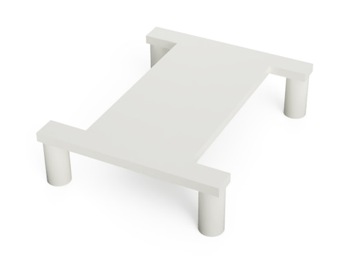 | 1 |
| Washer for IMU board mounting | 3D printed: stl step | 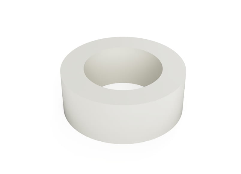 | 2 |
| Controller (recommended) | CC2500 transmitter, like BetaFPV LiteRadio CC2500 (RC receiver/Wi-Fi). Two-sticks gamepad (Wi-Fi only) — see recommended gamepads. Other⁵ | 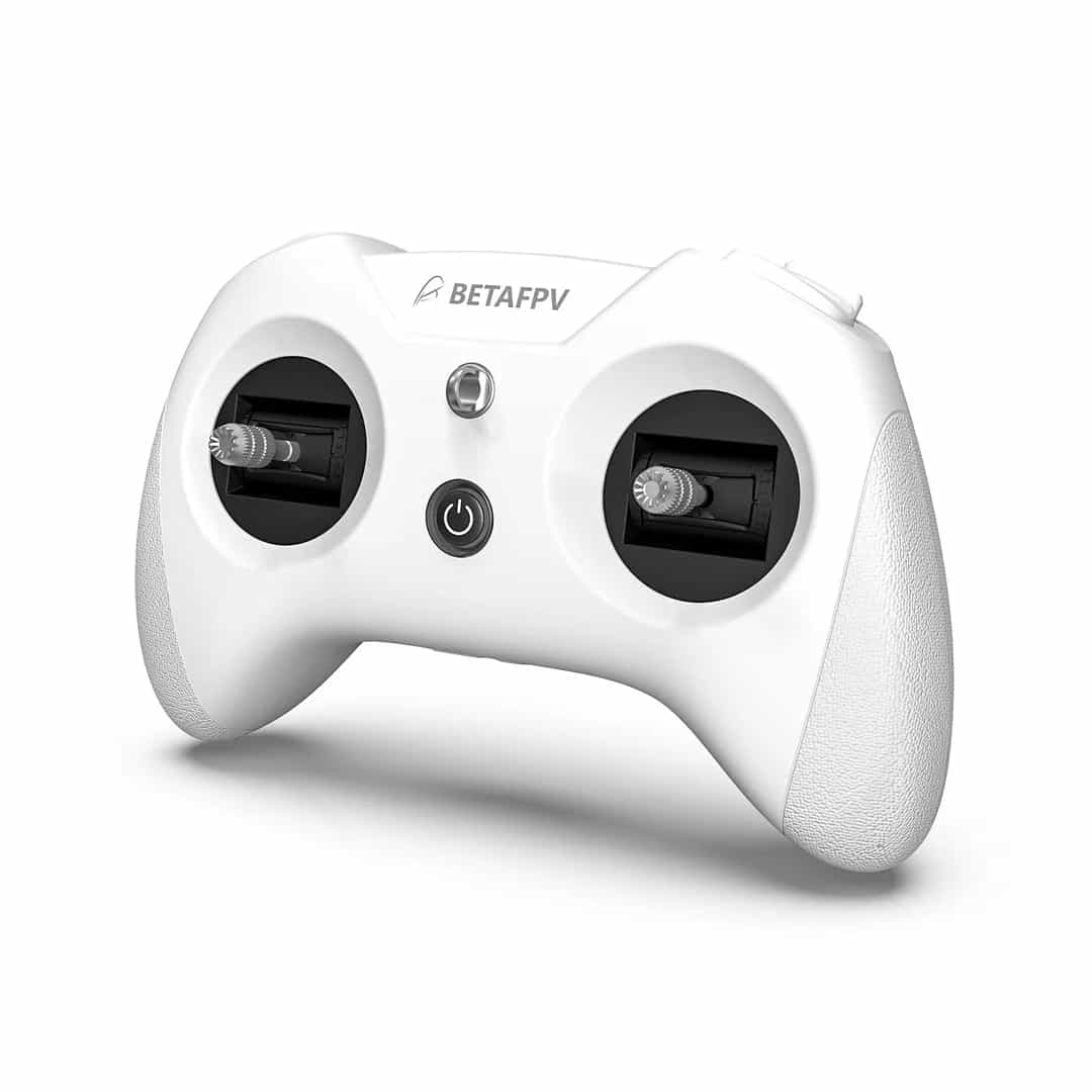 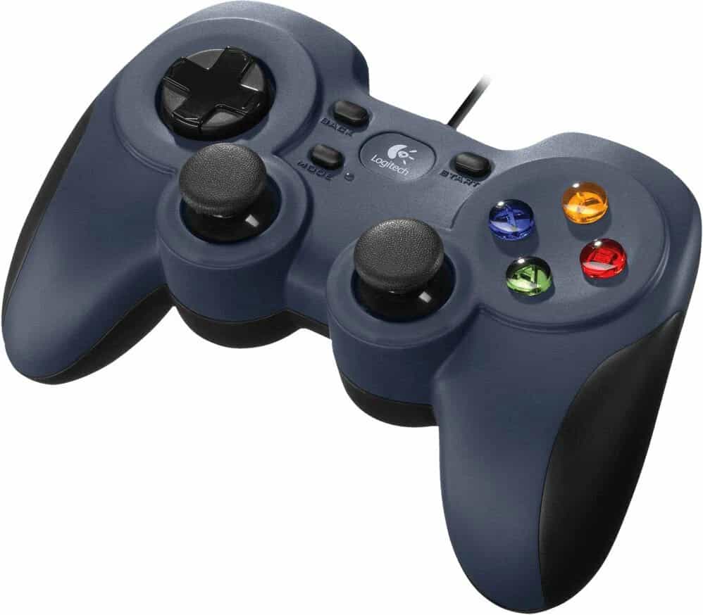 | 1 |
| RC receiver (optional) | DF500 or other³ | 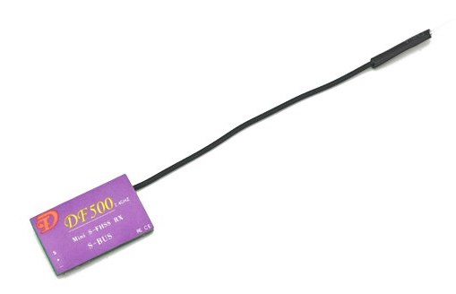 | 1 |
| Wires | 28 AWG recommended | 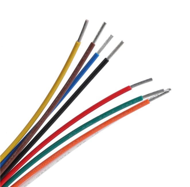 | |
| Tape, double-sided tape |
¹ — barometer is not used for now.
² — this frame is optimized for GY-91 board, if using other, the board mount holes positions should be modified.
³ — you also may use any transmitter-receiver pair with SBUS interface.
Tools required for assembly:
- 3D printer.
- Soldering iron.
- Solder wire (with flux).
- Screwdrivers.
- Multimeter.
Feel free to modify the design and or code, and create your own improved versions. Send your results to the official Telegram chat, or directly to the author (E-mail, Telegram).
Schematics
Simplified connection diagram

(Dashed elements are optional).
Motor connection scheme:
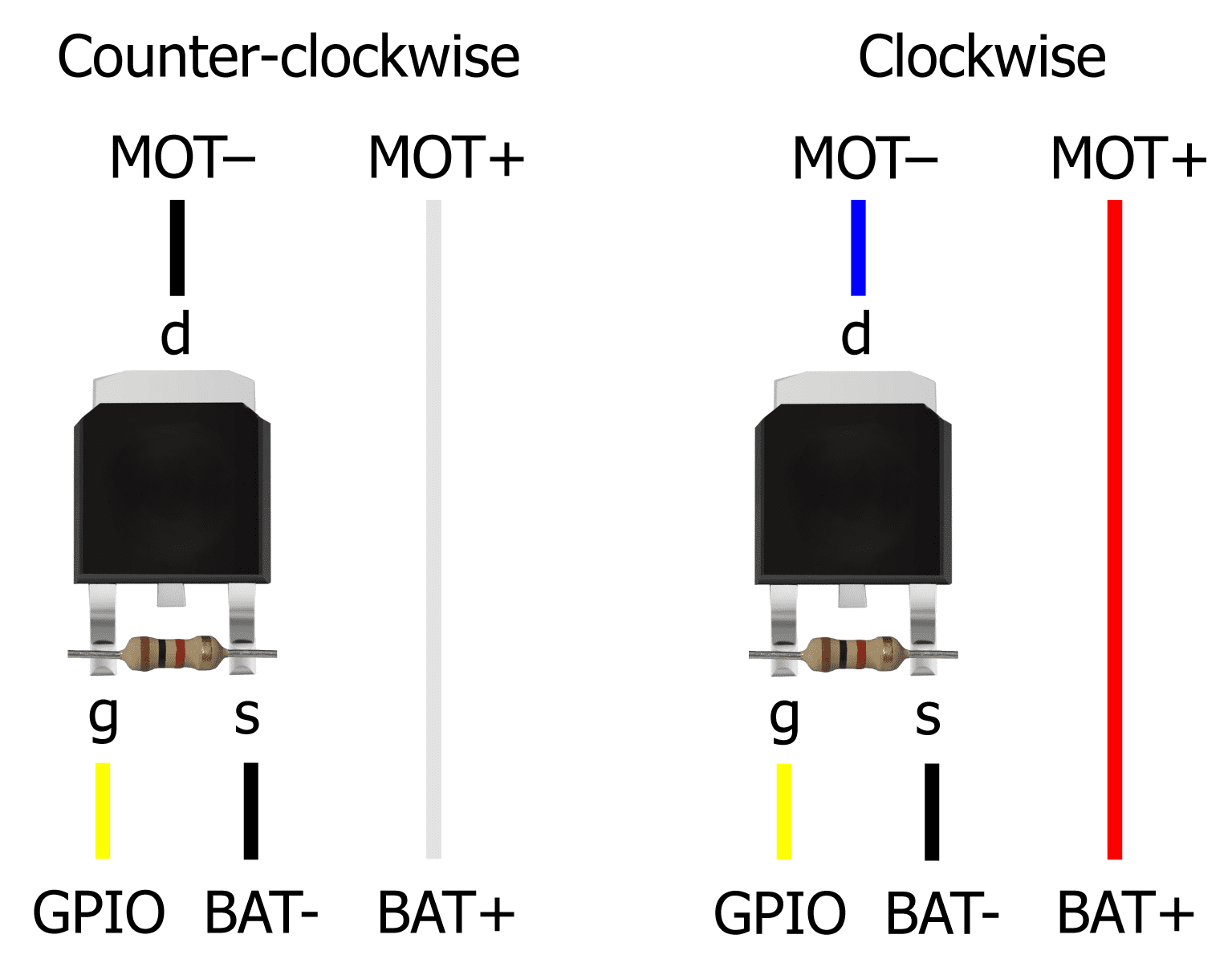
You can see a user-contributed variant of complete circuit diagram of the drone.
Notes
-
Power ESP32 Mini with Li-Po battery using VCC (+) and GND (-) pins.
-
Connect the IMU board to the ESP32 Mini using VSPI, power it using 3.3V and GND pins:
IMU pin ESP32 pin GND GND 3.3V 3.3V SCL (SCK) SVP (GPIO18) SDA (MOSI) GPIO23 SAO (MISO) GPIO19 NCS GPIO5 -
Solder pull-down resistors to the MOSFETs.
-
Connect the motors to the ESP32 Mini using MOSFETs, by following scheme:
Motor Position Direction Prop type Motor wires GPIO Motor 0 Rear left Counter-clockwise B Black & White GPIO12 (TDI) Motor 1 Rear right Clockwise A Blue & Red GPIO13 (TCK) Motor 2 Front right Counter-clockwise B Black & White GPIO14 (TMS) Motor 3 Front left Clockwise A Blue & Red GPIO15 (TD0) Clockwise motors have blue & red wires and correspond to propeller type A (marked on the propeller). Counter-clockwise motors have black & white wires correspond to propeller type B.
-
Optionally connect the RC receiver to the ESP32's UART2:
Receiver pin ESP32 pin GND GND VIN VCC (or 3.3V depending on the receiver) Signal (TX) GPIO4 -
Optionally connect the battery voltage divider for voltage monitoring to any ADC1 pin (e. g. GPIO32 on ESP32, GPIO3 on ESP32-S3).
ESP32 and ESP32-S3 can measure up to 3.1 V and ESP32-S3/ESP32-C3 can measure up to 2.5 V, so choose the voltage divider resistors accordingly.
Resources
- Telegram channel on developing the drone and the flight controller (in Russian): https://t.me/opensourcequadcopter.
- Official Telegram chat: https://t.me/opensourcequadcopterchat (English / Russian).
- Detailed article on Habr.com about the development of the drone (in Russian): https://habr.com/ru/articles/814127/.
Disclaimer
This is a DIY project, and I hope you find it interesting and useful. However, it's not easy to assemble and set up, and it's provided "as is" without any warranties. There's no guarantee that it will work perfectly, or even work at all.
⚠️ The author is not responsible for any damage, injury, or loss resulting from the use of this project. Use at your own risk!