WiFi Fan Controller
Smart fan control for your Home Assistant setup
A CE-certified, ESP32-based PWM fan controller designed for home server racks, media cabinets, and smart home projects. Control up to 4 fans with temperature-based automation, remote monitoring, and seamless Home Assistant integration.
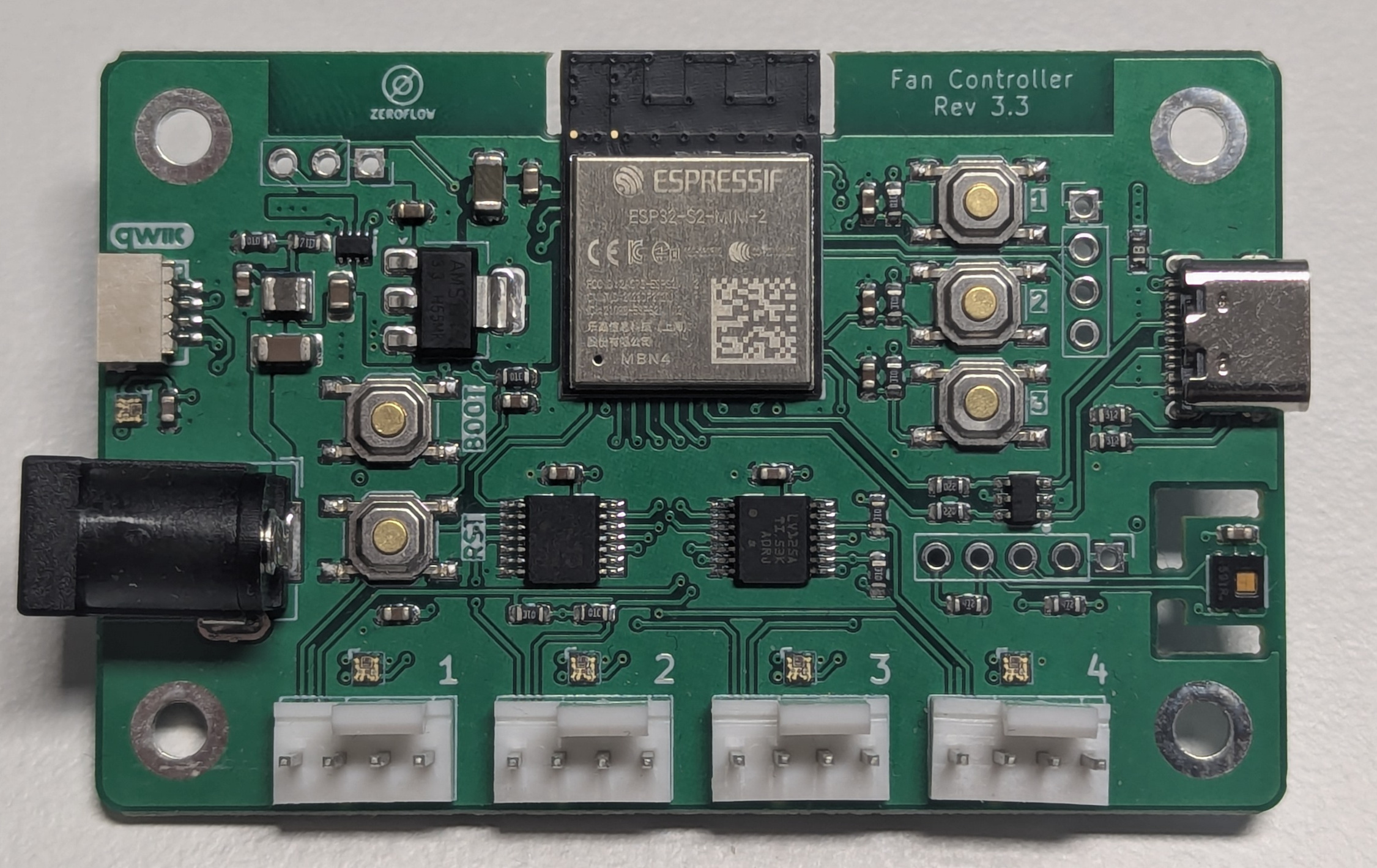
Why This Fan Controller?
Intelligent Climate Control: Automatically adjust fan speeds based on temperature and humidity readings from the integrated HDC1080 sensor. Turn fans off when equipment is idle, ramp up when things heat up.
Home Assistant Native: Built on ESPHome for seamless integration with Home Assistant. Monitor temperatures, adjust fan speeds, and create automations directly from your smart home dashboard.
Hackable & Expandable: Fully customizable ESPHome configuration with Qwiic and I2C expansion ports, NeoPixel output, user buttons, and GPIO breakouts. Add sensors, displays, or integrate with your existing projects.
Professional Quality: CE certified hardware with RGB status LEDs showing system status at a glance. Standard 12V DC barrel jack power input (5.5x2.1mm, centre positive).
Get Your Board
Ready to upgrade your setup?
Buy on Elecrow - $35.99 - Boards and 3D-printed cases available
Complete Documentation & Web Installer - Flash firmware directly from your browser
DIY Case: Print your own case using the WiFi Fancontroller Case design on Printables.com.
Power supply
The Fancontroller requires an external 12 V DC SELV power supply, not included.
- Connector: 5.5 × 2.1 mm barrel jack, centre positive
- Voltage: 12 V DC ±5 %
- Current: minimum 2.5 A recommended, depending on fan load
The power supply is not part of the product. Users must supply a power source that is certified for their region.
RF exposure
This product contains a radio transmitter. Install the product so that a separation distance of at least 20 cm is maintained between the antenna and any person during normal operation. This product is not intended to be worn on the body or operated in close proximity to the user.
User buttons
The board provides three user-assignable push buttons connected to GPIO. They have no function in the default configuration. Any behaviour is defined by the user's ESPHome configuration. Typical use is setup, commissioning, or occasional manual override; regular operation is via the network interface.
In the factory firmware the buttons are exposed to Home Assistant as binary sensors reporting their pressed state. They trigger no action on the board itself unless you configure one. See the USR Buttons module for one ready-made way to assign them.
Specifications
- Power
- External 12V DC SELV power supply, not included (see Power supply)
- 12V DC Barrel Input (5.5x2.1mm, centre positive)
- Max total input current: 2.5A (set by the DC barrel jack -- applies to the sum of all fans plus board load, not per fan header)
- Size your supply to the combined draw of the fans you connect, with headroom
- Low power operation: 0.25W typical, 0.07W deep sleep
- Fan Control
- 4× PWM Fan Outputs with RPM monitoring
- Supports standard 12V 4-pin PWM fans
- Sensors & I/O
- Integrated HDC1080 Temperature & Humidity Sensor
- RGB Status LEDs for board and fan ports (Rev 3.x)
- Qwiic Expansion Port for easy sensor additions
- I2C Expansion Port (2.54mm Header)
- 5V NeoPixel Output Port
- 3 User Buttons for custom functions
- GPIO Expansion Pads (2.54mm SMD Header)
- Connectivity
- WiFi (ESP32/ESP32-S2)
- USB-C for programming and power (Rev 2.0+)
Power Draw
The power usage of the device is dominated by the fans. As a standalone device, these are the measured power figures in different operation modes.
| Mode | Power Draw |
|---|---|
| Active Wifi Transfer (e.g. OTA Upload) | 0.6W |
| Wifi connected, power save mode deactivated (not default) | 0.52W |
Default Wifi connected, LEDs showing status (one-colored) | 0.25W |
| Wifi connected, LEDs off | 0.2W |
| Deep Sleep | 0.07W |
Disabling Wifi while not in deep sleep does not reduce power consumption, as the default light power save mode already does a good job.
These values have been measured via a DPS3005 power supply, therefore, their accuracy cannot be guaranteed.
Quick Start
All boards come pre-flashed with an ESPHome factory image that's ready to use:
- Power up the board via USB-C or 12V DC (USB-C is for flashing only, power via 12V DC barrel jack is required for fans)
- Connect to the WiFi hotspot (e.g.
fancontroller-r3-1-abcdef) - Configure your WiFi through the captive portal
- Done! Board appears in Home Assistant via ESPHome
What you get out of the box: The factory firmware exposes all 4 fan channels as speed controls in Home Assistant, along with temperature and humidity readings from the onboard sensor. Fan speeds can be adjusted manually from 0–100% or automated via Home Assistant. RPM monitoring is available for each fan port.
For custom firmware or troubleshooting, see Installation Methods below.
Identifying Your Board Revision
To choose the correct firmware, identify your board revision using the connectors:
| Revision | Left | Fan Ports | Right | Details | Notes |
|---|---|---|---|---|---|
| 1.0 | DC 12V | Fans | nothing | Link | |
| 2.0 | DC 12V, Status LED | Fans | USB-C | Link | |
| 3.0 | DC 12V, Status LED, QWIIC | Fans | USB-C | Link | |
| 3.1 | DC 12V, RGB Status LED, QWIIC | Fans, RGB Status LEDs | USB-C | Link | |
| 3.2 | DC 12V, RGB Status LED, QWIIC | Fans, RGB Status LEDs | USB-C | Link | Compatible firmware and pinout - hardware-only revisions |
| 3.3 | DC 12V, RGB Status LED, QWIIC | Fans, RGB Status LEDs | USB-C | Link | Compatible firmware and pinout - hardware-only revisions |
Installation Methods
Method 1: Web Installer (Recommended)
Flash pre-built firmware directly from your browser at fancontroller.arthofer.dev
Note for ESP32-S2 boards (Rev 2.0, 3.x): Web-based flashing may have connectivity issues. The most reliable web tool is ESPWEBTOOL by Spacehuhn. If the browser flash fails, use Method 2 (esptool) instead.
Method 2: esptool (Alternative for ESP32-S2)
Reliable flashing method, especially for ESP32-S2 boards:
- Install esptool:
pip install esptool - Download prebuilt binary from GitHub Releases
- Connect board via USB-C, hold BOOT button, press RESET
- Flash:
esptool.py --chip esp32s2 write_flash 0x0 firmware.bin - Press RESET to boot
Method 3: OTA Updates (After Initial Setup)
Once connected to WiFi, update wirelessly via ESPHome dashboard or web interface at http://[board-ip]
Method 4: ESPHome Hardware Packages (Custom Configurations)
For users who want to customize their configuration while keeping hardware setup simple. The hardware packages automatically configure all board-specific features for your revision.
This works by adding the following lines to your esphome config:
# Import the hardware package for your board revision
packages:
  fancontroller: github://zeroflow/wifi-fancontroller/hardware-rev-3.3.yaml@main
Example Configuration
Here's a complete example showing how to create a custom configuration using the hardware package:
# Import the hardware package for your board revision
packages:
  fancontroller: github://zeroflow/wifi-fancontroller/hardware-rev-3.3.yaml@main

esphome:
  name: my-fancontroller
  friendly_name: My Fan Controller

esp32:
  board: esp32-s2-saola-1  # Use esp32dev for Rev 1.0
  framework:
    type: arduino

# Enable logging
logger:

# Enable Home Assistant API
api:

# Enable OTA updates
ota:
  - platform: esphome

# Configure your WiFi
wifi:
  ssid: !secret wifi_ssid
  password: !secret wifi_password

  # Enable fallback hotspot
  ap: {}

captive_portal:
Available hardware packages:
- Rev 1.0:
hardware-rev-1.0.yaml(ESP32, esp32dev board) - Rev 2.0:
hardware-rev-2.0.yaml(ESP32-S2, esp32-s2-saola-1 board) - Rev 3.0:
hardware-rev-3.0.yaml(ESP32-S2, esp32-s2-saola-1 board) - Rev 3.1, 3.2, 3.3:
hardware-rev-3.3.yaml(ESP32-S2, esp32-s2-saola-1 board)
What's Included in Hardware Packages
The hardware package automatically configures all board features:
- 4× PWM fan outputs with speed control and RPM monitoring
- HDC1080 temperature & humidity sensor
- User buttons (USR1, USR2, USR3) for custom functions
- Status LEDs (RGB on Rev 3.x)
- NeoPixel output port (Rev 3.x)
- WiFi signal strength sensor
- All expansion ports and GPIO
No manual pin configuration needed - just import the package and customize your automations!
Fan Control Modules (advanced - click to expand)
Fan Control Modules
Beyond the basic hardware configuration, this project includes optional control modules that implement different fan control strategies. These modules can be imported into your configuration to add temperature-based fan control or status displays.
Available Modules
1. RPM Status LEDs (modules/rpm_status_leds.yaml)
Visual feedback module that updates each fan's RGB LED based on its RPM reading. LEDs sweep hue from red (stopped) through orange and yellow to green (full speed) using HSV color rotation, keeping the LED at full brightness at every point for vivid, easy-to-read colors.
Configuration Variables:
full_rpm: Maximum RPM for color scaling (default: 2500). At 0 RPM = red, at full_rpm = greenbrightness: LED brightness 0.0–1.0 (default: 0.5)update_interval: LED update frequency (default: 1s)fan1_led_enabled…fan4_led_enabled: Enable/disable each LED individually (default: true)
Example:
packages:
  rpm_status_leds:
    url: https://github.com/zeroflow/wifi-fancontroller
    ref: main
    files:
      - path: modules/rpm_status_leds.yaml
        vars:
          full_rpm: "2500"           # RPM value considered as 100% speed
          brightness: "0.3"          # Adjust for your environment
          fan3_led_enabled: "false"  # disable LED for unused fan channels
          fan4_led_enabled: "false"
2. Linear Temperature Control (modules/temperature_linear.yaml)
Simple linear fan control based on temperature. Creates a temperature curve with three zones:
- Below t_off: Fans off (0%)
- Between t_off and t1: Constant speed at fanpercent1
- Between t1 and t2: Linear ramp from fanpercent1 to fanpercent2
- Above t2: Constant speed at fanpercent2
Configuration Variables:
friendly_name: Device name prefix (default: "fancontroller")t_off: Temperature below which fans turn off (default: 25.0°C)t1: Lower temperature setpoint (default: 30.0°C)t2: Upper temperature setpoint (default: 50.0°C)fanpercent1: Fan speed % at t1 (default: 30.0%)fanpercent2: Fan speed % at t2 and above (default: 100.0%)
Features:
- Individual auto-control switches for each of 4 fans
- Output value sensor showing current calculated fan speed
Example:
packages:
  temperature_linear:
    url: https://github.com/zeroflow/wifi-fancontroller
    files:
      - path: modules/temperature_linear.yaml
        vars:
          friendly_name: "Server Rack"
          t_off: "25.0"        # Fans off below 25°C
          t1: "30.0"           # Start ramping at 30°C
          t2: "50.0"           # Full speed at 50°C
          fanpercent1: "30.0"  # Minimum speed: 30%
          fanpercent2: "100.0" # Maximum speed: 100%
3. PID Temperature Control (modules/temperature_pid.yaml)
Advanced PID (Proportional-Integral-Derivative) control for precise temperature regulation. Automatically adjusts fan speeds to maintain a target temperature with minimal overshoot.
Shoutout to patrickcollins12/esphome-fan-controller for the example code.
A PID simulator is available at https://fancontroller.arthofer.dev/pid-simulator. It uses simplified thermal models - treat results as a starting point for tuning.
Configuration Variables:
friendly_name: Device name prefix (default: "fancontroller")kp: Proportional gain coefficient (default: 0.39509)ki: Integral gain coefficient (default: 0.00470)kd: Derivative gain coefficient (default: 20.74267)max_integral: Maximum integral term value (default: 0.0)output_averaging_samples: Output averaging samples (default: 1)derivative_averaging_samples: Derivative averaging samples (default: 5)
Features:
- Climate entity (thermostat) for Home Assistant integration
- Live PID tuning via Home Assistant number entities
- Auto-tune button for automatic PID parameter calculation
- Deadband control to reduce oscillation near target
- Manual override fan control
- Individual PID control switches for each of 4 fans
- Real-time monitoring of P, I, D terms and error values
Example:
packages:
  temperature_pid:
    url: https://github.com/zeroflow/wifi-fancontroller
    files:
      - path: modules/temperature_pid.yaml
        vars:
          friendly_name: "Server Rack"
          kp: "0.39509"
          ki: "0.00470"
          kd: "20.74267"
Tuning Tips:
- Use the "PID Climate Autotune" button for automatic tuning
- Start with low kp/ki/kd values and increase gradually
- Monitor the P/I/D term sensors to understand controller behavior
4. RPM PI Control (modules/rpm_pi_control.yaml)
PI (Proportional-Integral) controller that regulates PWM output to achieve and maintain precise target RPM for each fan. Unlike percentage-based control, this module uses closed-loop feedback to compensate for fan aging, voltage variations, and load changes.
Important: This module uses the existing fan speed sensors from the hardware package. Since the default hardware sensors update every 10s with heavy filtering (too slow for stable PI control), you must override the sensor definitions in your config to use faster updates (2s recommended) and minimal filtering. See the example configuration below.
Configuration Variables:
friendly_name: Device name prefix (default: "fancontroller")kp: Proportional gain coefficient (default: 0.005)ki: Integral gain coefficient (default: 0.001)update_interval: Control loop update interval in seconds (default: 2, matches fast sensor update)
Features:
- Individual target RPM setpoints for each of 4 fans (0-4000 RPM range)
- Enable/disable PI control per fan with switches
- Live tuning of PI parameters via Home Assistant
- Real-time monitoring of error, P-term, I-term, and PWM output
- Anti-windup protection for integral term
- Configurable minimum PWM to prevent stalling
- Reset button for integral terms
Example:
packages:
  hardware:
    url: https://github.com/zeroflow/wifi-fancontroller
    ref: main
    files: [hardware-rev-3.1.yaml]
  rpm_pi_control:
    url: https://github.com/zeroflow/wifi-fancontroller
    ref: main
    files:
      - path: modules/rpm_pi_control.yaml
        vars:
          friendly_name: "Server Rack"
          kp: "0.005"           # Proportional gain
          ki: "0.001"           # Integral gain
          update_interval: "2s"  # Update every 2 seconds (matches sensor update)

# REQUIRED: Override hardware sensors for faster updates
sensor:
  - platform: pulse_counter
    id: fan1_speed
    pin: {number: GPIO16, mode: INPUT_PULLUP}
    update_interval: 2s
    filters:
      - multiply: 0.5
      - sliding_window_moving_average: {window_size: 3, send_every: 1}
  # Repeat for fan2_speed, fan3_speed, fan4_speed (see full example)
How to Use:
- Enable "PI Control Fan X" switch in Home Assistant
- Set "Fan X Target RPM" to your desired speed (e.g., 1500 RPM)
- The controller automatically adjusts PWM to maintain that speed
- Monitor debug sensors (Error, P-Term, I-Term, PWM Output) to verify operation
- Fine-tune Kp and Ki parameters if needed
Tuning Tips:
- Start with small kp (0.003-0.01) and ki (0.0005-0.002) values
- If fans respond too slowly: Increase Kp
- If fans oscillate around target: Decrease Kp or Ki
- If there's persistent error (actual RPM stays below/above target): Increase Ki
- Use "Reset PI Integrators" button when changing parameters or after long idle periods
- Monitor the debug sensors to understand controller behavior
5. Independent Triple Temperature Curves (modules/temperature_curve_triple_independent.yaml)
Three fully independent 5-point temperature curves, picked from Home Assistant with a "Curve Selection" select entity. Each profile carries its own temperature axis, its own speeds, and its own source sensor, so one profile can follow a heat pump flow temperature while another follows ambient room air. A profile whose speeds descend as temperature rises gives you an inverted curve, which is how you drive fans harder as water gets colder in cooling mode.
The sibling module modules/temperature_curve_triple.yaml shares one temperature axis across all three profiles. Use that one when the breakpoints stay fixed and only the aggressiveness changes; it does the job with 27 Home Assistant entities instead of 37.
Configuration Variables:
friendly_name: Device name prefix (default: "Fancontroller")curve_a_name/curve_b_name/curve_c_name: Profile display namescurve_a_temp[1-5]/curve_b_temp[1-5]/curve_c_temp[1-5]: Each profile's temperature axis, must be entered ascendingcurve_a_speed[1-5]/curve_b_speed[1-5]/curve_c_speed[1-5]: Each profile's speedscurve_a_sensor_id/curve_b_sensor_id/curve_c_sensor_id: ESPHomeidof the sensor each profile reads (default:fancontroller_temperature, the onboard HDC1080)
Features:
- Three independent 5-point profiles, no shared state between them
- Per-profile source sensor, including
platform: homeassistantsensors imported from Home Assistant - Linear interpolation between points; no runtime sorting
- Selection dispatches on the select index, so renaming a profile cannot break which curve is active
- Individual auto-control switches for each of 4 fans
- Output value sensor showing the active profile's calculated fan speed
- Unordered axis on any profile raises a warning sensor and names the profile in the log, but forces the fans to 100% only while that profile is the active one
- An unavailable source sensor holds the last good reading for 60 seconds, then forces 100%
Example:
packages:
  hardware:
    url: https://github.com/zeroflow/wifi-fancontroller
    ref: main
    files: [hardware-rev-3.1.yaml]
  temperature_curve_triple_independent:
    url: https://github.com/zeroflow/wifi-fancontroller
    ref: main
    files: [modules/temperature_curve_triple_independent.yaml]

# The sensors the profiles read, imported from Home Assistant
sensor:
  - platform: homeassistant
    id: hp_flow_temperature
    entity_id: sensor.heat_pump_flow_temperature
  - platform: homeassistant
    id: ambient_air_temperature
    entity_id: sensor.living_room_temperature

substitutions:
  curve_a_name: "Heating"
  curve_b_name: "Ventilation"
  curve_c_name: "Cooling"
  curve_a_sensor_id: "hp_flow_temperature"
  curve_b_sensor_id: "ambient_air_temperature"
  curve_c_sensor_id: "hp_flow_temperature"
  # Heating: flow temperature band, fans ramp up as the water gets hotter
  curve_a_temp1: "28.0"
  curve_a_temp5: "50.0"
  curve_a_speed1: "0.0"
  curve_a_speed5: "100.0"
  # Cooling: inverted. The AXIS still ascends, the SPEEDS descend.
  curve_c_temp1: "8.0"
  curve_c_temp5: "20.0"
  curve_c_speed1: "100.0"
  curve_c_speed5: "0.0"
  # ... points 2 to 4 omitted for brevity, see the full example
See examples/with-temperature-curve-triple-independent-rev-3.1.yaml for a complete configuration.
Important: never invert the temperature axis to build an inverted curve. Enter the temperatures ascending and let the speeds descend. An unordered axis is treated as a fault, not as a feature.
A curve_*_sensor_id naming an id that does not exist fails at compile time, not at config validation, and the error is confusing: it surfaces as a C++ 'my_sensor' was not declared in this scope pointing at generated code rather than at your YAML. Check the spelling of your sensor ids first if you see that. The value must be an ESPHome id:, not a Home Assistant entity_id.
Choosing a Control Module
- Linear Control: Best for simple setups where you want predictable fan behavior based on temperature zones. Easy to understand and configure.
- PID Temperature Control: Best for precise temperature control and systems where you want to maintain a specific target temperature with minimal fluctuation.
- Independent Triple Temperature Curves: Best when one board has to serve several operating modes that differ in more than aggressiveness, for example a heat pump that heats in winter and cools in summer, or profiles that read different sensors.
- RPM PI Control: Best when you need precise fan speed control in RPM, regardless of temperature. Ideal for applications requiring consistent airflow, compensating for fan aging, or when you want to set exact fan speeds.
- RPM Status LEDs: Can be combined with any control module to add visual feedback.
You can combine multiple modules in your configuration. For example:
- Use PID temperature control with RPM status LEDs for precise temperature regulation with visual feedback
- Use RPM PI control with temperature sensors to create a custom automation that sets target RPM based on temperature thresholds
- Combine linear temperature control with RPM status LEDs for simple automatic control with visual feedback
Ongoing Updates & Troubleshooting
Over-the-Air Updates: After initial setup, your board will appear in the ESPHome dashboard for wireless updates. No need to connect USB again.
Troubleshooting Discovery Issues: If your board doesn't appear in ESPHome after connecting to WiFi, check for mDNS issues on your network. You can work around this by manually specifying the board's IP address using the manual_ip configuration in your WiFi settings.
Need Help? Open an issue on GitHub or consult the ESPHome documentation.
Contributing
Found a bug or have a feature request? Open an issue or submit a pull request on GitHub.
License
ESPHome configuration: Copyright (C) 2026 Arthofer Engineering e.U.
Licensed under the GNU General Public License v3.0 – see LICENSE for details.
Hardware schematics (PDF): (C) 2026 Arthofer Engineering e.U.
All rights reserved. Provided for reference only.